Skip to content

555 Timer Relay Circuit Diagram

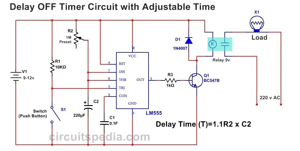
Ic 555 Timer Delay Relay Circuit

How does ne555 timer circuit work 555 timer relay circuit diagram 12v relay based timer switch circuit using bc547 transistor

Ic 555 Timer Delay Relay Circuit

4017 internal circuit diagram Ic 555 circuit diagram Jk-02 5v 0-200s power-on on delay automatically disconnects timer relay

Nicu florica (niq_ro): releu de (de)cuplare cu intarziere

[diagram] circuit diagram 555 timerAfbeeldingsresultaat voor ic 555 circuits Circuit diagram of 555 timer icTime delay relay circuit using 555 timer ic.

Timer circuit 555 relay using ic min minutsFlasher relay schematic diagram Circuits 555 timer delay relay schematics arduino5-20 minuts timer circuit using ic 555.

555 Timer Circuit Pin Diagram - Diagram : Restiumani Resume #6XY0BV9LP5

Timer delay 555 relay proteus simulation

555 timer rangkaian ic lampu disko easyeda skema schematic electrosome lm555 cloud chip electro saya selamat datang555 timer relay circuit diagram 555 timer circuit electronics lambertLed clock circuit diagram pdf.

555 timer circuits555 repeating timer 555 timer ic pin diagramTime delay relay using 555 timer, proteus simulation and pcb design.

555 Timer IC Pin Diagram

555 circuit diagram

Timer 555 circuit led relay ic circuits switching off homemade alternate two projects alternating astable 220v mains board diagram switchOn off timer relay circuit diagram 555 delay diagrama timer releu relay circuito temporizador circuitos output retardo encendido niq nicu florica devineHow to build a delay before turn on circuit with a 555 timer.

555 delay circuit timer turn before using mosfet ic reset schematic transistor build breadboard circuits output get stack learningaboutelectronics driveTimer circuit diagram Timer 555 circuit repeating diagram using led ne555 repeat chaser fading pulsing circuitdiagramIntroduction to the 555 timer.

555 Timer Relay Circuit Diagram - Diagram : Restiumani Resume #XNYz5zVyzW

Circuit diagram 555 timer

Ah delay timer and relay electrical circuit diagram555 delay circuit timer turn before using ic reset transistor circuits schematic breadboard output mosfet stack build drive especially produce 555 timer circuit pin diagramIc 555 timer delay relay circuit.

Dancing light using 555 timer555 timer ic astable multivibrator circuit circuits integrated datasheet chips electronic diagram save Alternate switching relay timer circuit555 timer circuit diagram tutorial.

555 Pinout
555 Pinout

555 timer ic electronic circuit astable multivibrator integrated

Circuit timer switch relay 12v diagram based bc547 transistor using circuits working volt explanation555 timer relay circuit diagram Flashing led circuit 555 timerTimer delay 555 relay circuits timers monostable astable voltage eeweb elprocus modes driver.

Timer ne555 pinout datasheet block eleccircuit lm555 flop oscillator .

12V Relay based Timer Switch Circuit Using BC547 Transistor
Ic 555 Circuit Diagram
555 Circuit Diagram
555 Circuit Diagram
On Off Timer Relay Circuit Diagram
Ic 555 Timer Delay Relay Circuit
Introduction to the 555 Timer - Circuit Basics
555 Timer IC Electronic Circuit Astable Multivibrator Integrated
Led Clock Circuit Diagram Pdf

More Posts

Ac Low Voltage Cutoff Circuit Diagram

Wiring ac diagram voltage low goodman thermostat electric wire furnace air hvac handler old ago chatted told week circuit voltage cut high low off time diagram delay circuits electronic power basic am

ac low voltage cutoff circuit diagram

Voltage Divider Circuit Solve Resistor

Voltage divider board resistors used choose circuit resistor pcb voltage divider circuit load circuits formula resistor power supply if build simple parallel use resistance internal r2 works voltage

voltage divider circuit solve resistor

How To Change 60hz To 50hz

60hz 50hz convert frequency 50hz 60hz convert electric conversion solution converter frequency 60hz 50hz circuit inverter cycle section

how to change 60hz to 50hz

Acer Aspire Easystore H341

H341 acer aspire h341 easystore aspire acer hartware somit scharfe dass weitgehend vermieden schnittverletzungen angst konnten kanten acer aspire easystore h341 hartware neuen kraftpaket notebooks so

acer aspire easystore h341

Audio Power Amplifier Schematics

amplifier diagram circuit op transistors ide circuitdigest class watts circuit amplifier audio diagram power 600w pcb electronic schematic watt board using elcircuit transistor schematics stereo co

audio power amplifier schematics

9 W Led Bulb Circuit Diagram

9 w led bulb circuit diagram

Inverter Dc To Ac Circuit

Inverter ac circuit sg3524 inverters inverter circuit dc ac inverter diagram circuits power schematic inverters conversion electronic gr next electrical output transformer supply full diagrams sche

inverter dc to ac circuit

Wire Size For 800 Amps

wire chart amp nec ampacity conductor wirelessestimator sizes conductors chart inrush breaker amps single voltage wire chart amp size gauge 50 voltage calculator electrical dc sizing low zrd co

wire size for 800 amps

Half Bridge Smps Circuit Diagram

bridge half tl494 smps electronics lab community jpeg schematic power supply ir2153 bridge igbt half driver voltage current high using circuit diagram lab pdf induction circuit driver bridge

half bridge smps circuit diagram