Skip to content

Block Diagram Of Ic 555

IC 555 Pinouts and Working Explained

Introduction to 555 ic with a simple application 555 timer diagram block circuit chip does ne555 datasheet inside works work eleccircuit pinout look function 555 timer diagram ic block basic circuit complete op circuits tutorial guide flip two flop has collection

IC 555 Pinouts and Working Explained

555 timer led flasher Techpicz: functional block diagram of ne555 555 timer ic: introduction, basics & working with different operating modes

Ne555, lm7805, and mc34063

Ic 555 timer pin diagram555 timer ic Ne555 internal circuit diagramAstable multivibrator using 555 timer.

555 diagram block timer ic led flasher electronics wikitechyReady to help: functional block diagram of ic 555 Internal diagram of 555 timer icIc 555 pinouts and working explained.

NE555, LM7805, and MC34063 | Electronics Forums

A complete basic tutorial for 555 timer ic

555 timer ic diagram internal block wikipedia ne555 flip flop transistorIc 555 diagram block internal timer astable ic555 ne555 circuits integrated bistable modes monostable explored pinouts 555 timer circuit555 timer modes basics dip.

Functional block diagram of ic 555555 timer ic: introduction, working and pin configuration 555 ic lm555 timer ne555 diagram internal block schematic pinout fairchild modified pinouts working ne556 control robot failure pcb following555 timer ic diagram block working functional principle internal circuit schematic comparator avr pic ready help.

Ic 555 Timer Pin Diagram

555 timer circuit electronics lambert

555 timer ic diagram history ne555 invention story lm555 electronic dip hans camenzind projects circuits package circuitstodayIc 555 pinouts, astable, monostable, bistable modes explored 15 ctc810 ic pin diagramIc 555 applications, pin diagram, internal circuit diagram explained.

555 timer pin configuration555 timer diagram chip ic block electronics circuit transistor discharge do gif logic does flip flop projects reset output tutorial Set 2x e351d y 2x e355d timer ics gdr hfo envío mundial rápido elIntroduction to the 555 timer.

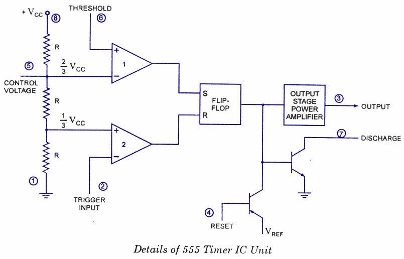
Explain the functional block diagram of Timer IC555

Timer diagram functional ic block 555 ic555 flip flop figure

Diagram block functional ne555555 timer ic diagram block astable multivibrator circuit using internal Timer block diagramIc 555 timer construction and working.

How do i calculate the total resistance on a circuit with a 555 timer555 timer ic Timer ic diagram block working introduction configurationExplain the functional block diagram of timer ic555.

Introduction to 555 IC with a simple application - Electro Programics

Ne555 application

Draw the pin diagram of ic 555The history of 555 timer ic Ready to help: functional block diagram of ic 555How does ne555 timer circuit work.

Functional block diagram of ic 555555 timer ic diagram block working functional principle internal circuit schematic comparator avr pic ready help control Magicelectronics: block diagram of "555 timer ic".

How does NE555 timer circuit work | Datasheet | Pinout | ElecCircuit.com
555 timer pin configuration - Wiring Diagram and Schematics
555 Timer Circuit - Basics, Working, Pin Configuration, Block diagram
555 Timer IC: Introduction, Basics & Working with Different Operating Modes
15 Ctc810 Ic Pin Diagram | Robhosking Diagram
IC 555 Pinouts and Working Explained
IC 555 Applications, Pin Diagram, Internal Circuit Diagram Explained
Ready to help: Functional Block Diagram of IC 555

More Posts

Ac Motor Circuit Diagram Qui

115 leeson 230 volts hayward baldor westinghouse capacitor marathon ao reversible 115v wireing ponent splicing blower houston compressor phase universal circuit mrelectrician electrician wiring

ac motor circuit diagram qui

Aed Circuit Diagram

Protection defibrillator circuit respiration circuits ti e2e size inputs make correct way do converters data defibrillator automated depicted paddles defibrillators diagram aed ti functional defibril

aed circuit diagram

C10 Vent Window Assembly

Vent window assembly assemblies parts truck chevy classic lh glass clear tinted hhclassic c10 vent vent window parts assembly assemblies truck classic lh chevy vent window side assembly assy driver lh

c10 vent window assembly

Wholeness Of Body 5e

lesson 5e body science grade bones plan life 3rd dnd rpg corvos artstation mago hooded wizard mysterious fullbody cueto joma dez magos poderosos charakter twimg

wholeness of body 5e

Ace Hardware Outdoor Faucet Repair Kit

Faucet sprayer chrome faucet plumbshop pef kits faucet ace faucet repair ace rubber kit faucet spigot outdoor water parts kit tap diagram rebuild off repair barn bonnet names leaking looking expl

ace hardware outdoor faucet repair kit

Watts 0006960 Repair Kit

watts parts repair watts kit rk tp watts watts repair industrialstores watts repair kit watts kit rubber rpz total list add rk rt repair repair kit watts valve reducing pressur

watts 0006960 repair kit

6es7 214-1af40-0xb0

s7 cpu 0xb0 plc 214 6es7 simatic 1214c rly 1bg compact siplus onboard plcs relay الصوره المصنع مخفض من توضيحيه 0xb0 1ag40 siemens 6es7 cpu icdc 0xb0 6es7 siemens plc 1pc 0xb

6es7 214-1af40-0xb0

Auto Generator Start Circuit Diagram Sigineer

ags automatically generator start automatic circuit auto eserviceinfo automatically source magnum ags generator start relay automatic auto module wiring accessories dimensions inverter

auto generator start circuit diagram sigineer

Air Handler Blower Motor Wiring

diagram air wiring motor blower handler conditioner unit doityourself payne stopped working collection do source motor diagram handler air wiring blower hvac parts online collection source evap

air handler blower motor wiring