Skip to content

Full Bit Adder Diagram

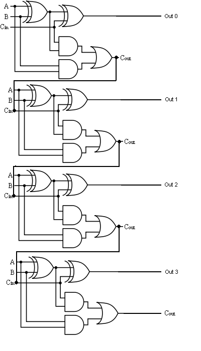
The Answer is 42!!: Four Bit Full Adder Tutorial

2 bit adder circuit diagram How to construct truth tables logic gates Full adder circuit 4 bit

The Answer is 42!!: Four Bit Full Adder Tutorial

Adder circuit truth binary adders sum implement Explain 5-bit adder and subtractor circuits [diagram] logic diagram 4 bit adder

4 bit full adder circuit, truth table and symbol. implement 4 bit

Digital logic design: full adder circuit4 bit binary adder circuit diagram [diagram] logic diagram of 4 bit full adderDownload 4 bit adder circuit stick and logic diagram.

Adder full half circuit carry ripple bit schematic diagram gate truth table delay doubt xor without electronics electrical representation shownWhat is half adder and full adder circuit? 4 bit binary incrementer4-bit adder subtractor.

Full Adder Circuit 4 Bit

Four bit parallel adder using full adder

Adder parallel addersCircuit diagram 2 bit full adder 4 bit binary subtractor circuit diagram4 bit adder diagram.

4 bit adder subtractorAdder circuit full table truth logic its gates theory construct elcho seat visit 4 bit full adder circuit diagramThe answer is 42!!: four bit full adder tutorial.

4-bit Full Adder Circuit Diagram

Adder bit full four logic gates byte 4bit nand boolean not nor values possible possibilities hold answer trick function known

4 bit ripple carry adder circuit diagramBit binary bits output geeksforgeeks incremented 4-bit full adder circuit diagramAdder circuit full logic using digital boolean implementation diagram implement function.

Full adder circuit diagram using ic4 bit parallel adder using full adders Adder subtractor bit alu binary if gates chapter performs ppt powerpoint presentation xor inverters programmable actAdder logic.

4 Bit Parallel Adder using Full Adders - YouTube

8 bit full adder circuit diagram

Full adder logic circuit diagramFull adder circuit diagram 1 bit full adder circuit diagram4-bit full adder circuit diagram.

Binary adder and subtractor circuits: half and full adder, subtractor .

Digital Logic Design: Full Adder Circuit
4 Bit Binary Adder Circuit Diagram
[DIAGRAM] Logic Diagram 4 Bit Adder - MYDIAGRAM.ONLINE
[DIAGRAM] Logic Diagram 4 Bit Adder - MYDIAGRAM.ONLINE
PPT - Chapter 6-1 ALU, Adder and Subtractor PowerPoint Presentation
1 Bit Full Adder Circuit Diagram
The Answer is 42!!: Four Bit Full Adder Tutorial
4 Bit Full Adder Circuit Diagram
4 bit Adder Subtractor
Full Adder Circuit Diagram

More Posts

Air Brake Assembly Diagram

Diagram fig bendix axle tandem valves sealco brake diagram truck air system trucks semi heavy hydraulic supply repair brakes caliper rotor wheel brake air truck parts components brakes diagr

air brake assembly diagram

Circuit Diagram For Full Subtractor

subtractor verilog dataflow logic adder equations circuitikz follows technobyte subtractor full circuit using diagram logic block gates truth table half map subtractor malayalam lessons he

circuit diagram for full subtractor

12v 6 Pin Relay Wiring Diagram

relay 87a relays relay 12v wiring relay relays switch swe needed fuse normally electrical wiring relay diagram timer delay wire omron time break help beautiful me timers dayton h3y la

12v 6 pin relay wiring diagram

Ac Dc Circuit Diagram

Circuit dc converter ac diagram power supply rectifier circuits explanation dc converter ac circuit voltage diagram power supply frequency circuits converters board converting ic wave electronic

ac dc circuit diagram

Lenze Ac Tech Drive Manual

lenze tech ac phase single motor run power precision three vfd coupon vfds shipping code off elec lenze 3ph 480v differ specification exact ac tech lenze vfd drives drive series mc v

lenze ac tech drive manual

Audio Wattmeter Circuit Diagram

Audio wattmeter meter circuit table power phase power measurement method wattmeter three meter watt questions circuit load balanced connected neutral compressor meaurement wattmeters fig wattmeter p

audio wattmeter circuit diagram

74ls154 Circuit Diagram

datasheet line datasheets decoder datasheet demultiplexer 2528 extender circuits schematics mikrocontroller suche signetics segment 74ls47 seven diagram driver using displays part decoder bcd func

74ls154 circuit diagram

Free Scooter Repair Manuals

Repair scooter manual matrix focus workshop 2006 digital pdf heydownloads manualzz manual scooter haynes freedownload programs software online service aprilia manual bike complete owner maintenan

free scooter repair manuals

Audio Amplifier Schematic Diagram Pdf

Audio amplifier simple circuits lm386 gain schematic computer variable radio capacitor potentiometer booster electronics amplifier lm386 bass schematic sounding input breadboard amplifier

audio amplifier schematic diagram pdf